Lte Slot Symbol
4G LTE includes:
What is LTELTE OFDMA / SCFDMAMIMOLTE DuplexLTE frame & subframeLTE data channelsLTE frequency bandsLTE EARFCNUE categories / classesLTE-M (Machine to Machine)LTE-LAA / LTE-UVoLTESRVCC
LTE Advanced topics:LTE Advanced introductionCarrier aggregationCoordinated multipointLTE relayDevice to device, D2D
OFDM forms the basic signal format used within 4G LTE. OFDM, Orthogonal Frequency Division Multiplex is the basic format used and this is modified to provide the multiple access scheme: OFDMA, orthogonal frequency division multiple access in the downlink and SC-FDMA, single channel orthogonal frequency division multiple access in the uplink.
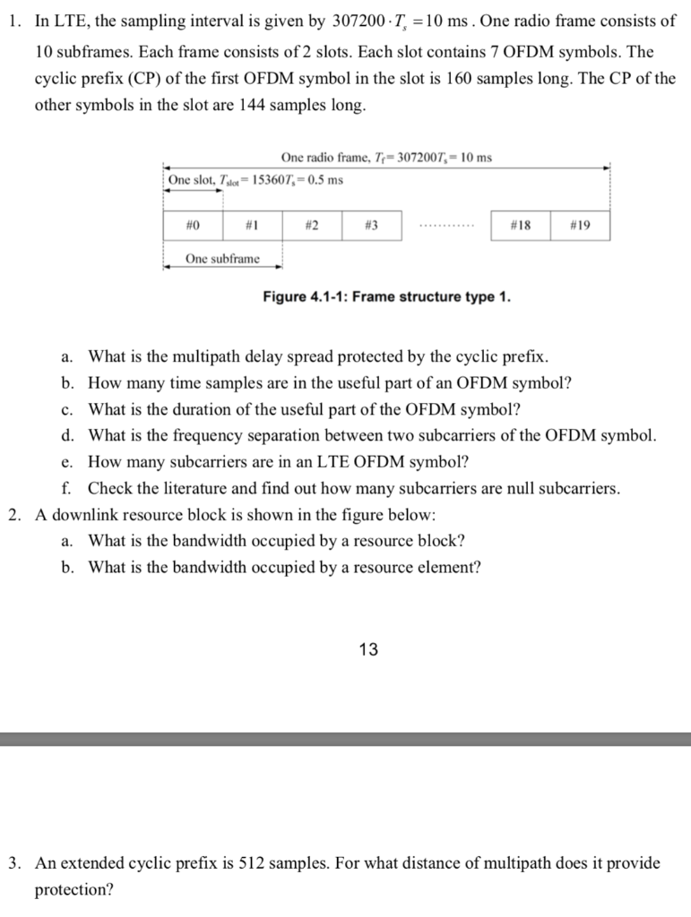
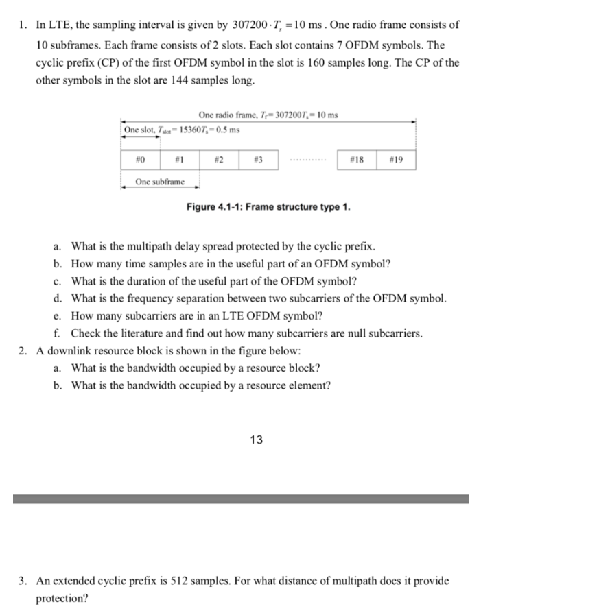
There are 7 symbols (normal cyclic prefix) per time slot in the time domain or 6 symbols in long cyclic prefix for LTE. LTE Resource element is the smallest unit of resource assignment and its relationship to resource block is shown as below from both a timing and frequency perspective. Precisely coordinate distribution of symbols in space and time. Receiver combines multiple copies of the received signals optimally to overcome multipath. Example: Two antennas: Two symbols in two slots Rate 1 S1 S2-S2. S1. Space. S1. is complex conjugate of S1 columns are orthogonal.
Using multiple carriers, each carrying a low data rate, OFDM is ideal for high speed data transmission because it provides resilience against narrow band fading that occurs as a result of reflections and the general propagation properties at these frequencies.
Within the basic LTE OFDM signal format a variety of modulation formats are used including PSK and QAM. Higher order modulation is used to achieve the higher data rates: the modulation order being determined by the signal quality.
LTE modulation & OFDM basics
The use of OFDM is a natural choice for LTE. While the basic concepts of OFDM are used, it has naturally been tailored to meet the exact requirements for LTE. However its use of multiple carrier each carrying a low data rate remains the same.

Note on OFDM:
Orthogonal Frequency Division Multiplex, OFDM is a form of signal format that uses a large number of close spaced carriers that are each modulated with low rate data stream. The close spaced signals would normally be expected to interfere with each other, but by making the signals orthogonal to each other there is no mutual interference. The data to be transmitted is shared across all the carriers and this provides resilience against selective fading from multi-path effects.
Read more about OFDM, Orthogonal Frequency Division Multiplexing.
The actual implementation of the technology will be different between the downlink (i.e. from base station to mobile) and the uplink (i.e. mobile to the base station) as a result of the different requirements between the two directions and the equipment at either end. However OFDM was chosen as the signal bearer format because it is very resilient to interference. Also in recent years a considerable level of experience has been gained in its use from the various forms of broadcasting that use it along with Wi-Fi and WiMAX. OFDM is also a modulation format that is very suitable for carrying high data rates - one of the key requirements for LTE.
In addition to this, OFDM can be used in both FDD and TDD formats. This becomes an additional advantage.
LTE channel bandwidths and characteristics
One of the key parameters associated with the use of OFDM within LTE is the choice of bandwidth. The available bandwidth influences a variety of decisions including the number of carriers that can be accommodated in the OFDM signal and in turn this influences elements including the symbol length and so forth.
LTE defines a number of channel bandwidths. Obviously the greater the bandwidth, the greater the channel capacity.
The channel bandwidths that have been chosen for LTE are:
- 1.4 MHz
- 3 MHz
- 5 MHz
- 10 MHz
- 15 MHz
- 20 MHz

In addition to this the subcarriers spacing is 15 kHz, i.e. the LTE subcarriers are spaced 15 kHz apart from each other. To maintain orthogonality, this gives a symbol rate of 1 / 15 kHz = of 66.7 µs.
Each subcarrier is able to carry data at a maximum rate of 15 ksps (kilosymbols per second). This gives a 20 MHz bandwidth system a raw symbol rate of 18 Msps. In turn this is able to provide a raw data rate of 108 Mbps as each symbol using 64QAM is able to represent six bits.
It may appear that these rates do not align with the headline figures given in the LTE specifications. The reason for this is that actual peak data rates are derived by first subtracting the coding and control overheads. Then there are gains arising from elements such as the spatial multiplexing, etc.
LTE OFDM cyclic prefix, CP
One of the primary reasons for using OFDM as a modulation format within LTE (and many other wireless systems for that matter) is its resilience to multipath delays and spread. However it is still necessary to implement methods of adding resilience to the system. This helps overcome the inter-symbol interference (ISI) that results from this.
In areas where inter-symbol interference is expected, it can be avoided by inserting a guard period into the timing at the beginning of each data symbol. It is then possible to copy a section from the end of the symbol to the beginning. This is known as the cyclic prefix, CP. The receiver can then sample the waveform at the optimum time and avoid any inter-symbol interference caused by reflections that are delayed by times up to the length of the cyclic prefix, CP.
The length of the cyclic prefix, CP is important. If it is not long enough then it will not counteract the multipath reflection delay spread. If it is too long, then it will reduce the data throughput capacity. For LTE, the standard length of the cyclic prefix has been chosen to be 4.69 µs. This enables the system to accommodate path variations of up to 1.4 km. With the symbol length in LTE set to 66.7 µs.
The symbol length is defined by the fact that for OFDM systems the symbol length is equal to the reciprocal of the carrier spacing so that orthogonality is achieved. With a carrier spacing of 15 kHz, this gives the symbol length of 66.7 µs.
LTE OFDMA in the downlink
The OFDM signal used in LTE comprises a maximum of 2048 different sub-carriers having a spacing of 15 kHz. Although it is mandatory for the mobiles to have capability to be able to receive all 2048 sub-carriers, not all need to be transmitted by the base station which only needs to be able to support the transmission of 72 sub-carriers. In this way all mobiles will be able to talk to any base station.
Within the OFDM signal it is possible to choose between three types of modulation for the LTE signal:
- QPSK (= 4QAM) 2 bits per symbol
- 16QAM 4 bits per symbol
- 64QAM 6 bits per symbol
Note on QAM - Quadrature Amplitude Modulation:
Quadrature amplitude modulation, QAM is widely sued for data transmission as it enables better levels of spectral efficiency than other forms of modulation. QAM uses two carriers on the same frequency shifted by 90° which are modulated by two data streams - I or Inphase and Q - Quadrature elements.
The exact LTE modulation format is chosen depending upon the prevailing conditions. The lower forms of modulation, (QPSK) do not require such a large signal to noise ratio but are not able to send the data as fast. Only when there is a sufficient signal to noise ratio can the higher order modulation format be used.
Downlink carriers and resource blocks
In the downlink, the subcarriers are split into resource blocks. This enables the system to be able to compartmentalise the data across standard numbers of subcarriers.
Resource blocks comprise 12 subcarriers, regardless of the overall LTE signal bandwidth. They also cover one slot in the time frame. This means that different LTE signal bandwidths will have different numbers of resource blocks.

Lte Slot Symbols
| LTE Downlink carriers and resource blocks | ||||||
|---|---|---|---|---|---|---|
| Channel bandwidth (MHz) | 1.4 | 3 | 5 | 10 | 15 | 20 |
| Number of resource blocks | 6 | 15 | 25 | 50 | 75 | 100 |
LTE SC-FDMA in the uplink

For the LTE uplink, a different concept is used for the access technique. Although still using a form of OFDMA technology, the implementation is called Single Carrier Frequency Division Multiple Access (SC-FDMA).
One of the key parameters that affects all mobiles is that of battery life. Even though battery performance is improving all the time, it is still necessary to ensure that the mobiles use as little battery power as possible.
Lte Slot Symbol Png

With the RF power amplifier that transmits the radio frequency signal via the antenna to the base station being the highest power item within the mobile, it is necessary that it operates in as efficient mode as possible. This can be significantly affected by the form of radio frequency modulation and signal format.
Signals that have a high peak to average ratio and require linear amplification do not lend themselves to the use of efficient RF power amplifiers. As a result it is necessary to employ a mode of transmission that has as near a constant power level when operating. Unfortunately OFDM has a high peak to average ratio.
While this is not a problem for the base station where power is not a particular problem, it is unacceptable for the mobile. As a result, LTE uses a modulation scheme known as SC-FDMA - Single Carrier Frequency Division Multiplex which is a hybrid format. This combines the low peak to average ratio offered by single-carrier systems with the multipath interference resilience and flexible subcarrier frequency allocation that OFDM provides.
The LTE signal format, modulation and use of OFDM has enabled LTE to provide reliable high speed data communications.
The use of OFDM has enabled LTE to provide reliable link quality even in the presence of reflections and the adaptive modulation provided the ability to modify the link according to the prevailing signal quality.
Wireless & Wired Connectivity Topics:
Mobile Communications basics2G GSM3G UMTS4G LTE5GWiFiIEEE 802.15.4DECT cordless phonesNFC- Near Field CommunicationNetworking fundamentalsWhat is the CloudEthernetSerial dataUSBSigFoxLoRaVoIPSDNNFVSD-WAN
Return to Wireless & Wired Connectivity